Aircraft Gas Turbine Engine Spinner
The function of aircraft gas turbine engine spinner is to direct air radially outward from the center of fan blade hub into fan blade assembly so that blade can accelerate the air.
Aircraft gas turbine engine operated under temperature and humidity condition which could promote formation of substinitial layer of ice on the surface of engine spinner , thereby seriously disturbing incoming airflow to compressor which cause stall or surge and this lead to engine flame out.The anti-ice or de-ice system is used to prevent spinner from ice .
The formation of ice depends on shape of spinner. Thus , the method which is used to prevent the ice formation also depends on spinner shape.The normal spinner shape used in modern aircraft gas turbine engine are elliptical, conical and coniptical .
Elliptical Spinner :

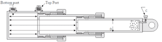
An elliptical spinner is more efficient than other spinner but ice formation start at a lower humidity as compared to other spinner design. The stagnation point on elliptical spinner form at front end of spinner which cause formation of ice on spinner surface. Due higher risk of ice formation. spinner usually heated with warm air to prevent it from ice.The heat air for spinner anti-ice is tapped from low pressure compressor and flow into spinner cavity.The airflow exit from the spinner holes located just in front of the rear edge of the spinner. The example of such spinner is PW 1000 Gear Turbofan engine.
Conical Spinner :

A higher level of humidity is necessary for ice formation on a conical spinner.The stagnation point form at spinner tip and is nearly zero on conical spinner and airflow moves almost parallel to the surface of the spinner. The ice form on conical spinner tip at higher humidity with right air temperature. To prevent this ice formation , the spinner tip is made from elastic rubber.The elastic rubber tip will act like de-icing device.The basic working principle of elastic rubber spinner tip as de-icing device is ice builds on a rotating rubber tip will unsymmetrical to the axis of rotation. When ice formation start on unsymmetrical rubber tip , the spinner tip is deformed by centrifugal force of ice.Thus, the ice flakes off and the ice formation on such a spinner cannot spread behind the elastic rubber tip. A conical spinner is aerodynamically not as efficient as the elliptical spinner but ice formation is a rare problem during an aircraft operation.The example of such spinner is IAE 2500 Turbofan engine.
Coniptical Spinner :

Please Follow me and Join me on Telegram there you can share your doubt.
https://t.me/joinchat/NxLqTH2cTX9hMjM1
You can also Join me Facebook Group, Link provided below.
https://www.facebook.com/groups/304288677920172/?ref=share
Join us on Instagram link below
https://www.instagram.com/invites/contact/?i=1tv1l3w2dcogj&utm_content=m7ttk5x
Youtube Channel
https://www.youtube.com/channel/UCwfz-cO2H3k8tnA_CMrMKtw

Superb info sir
ReplyDeleteU r a great man
ReplyDeleteSuperb explanation 👌👌
ReplyDelete