Posts

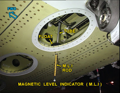
Procedure for calculating fuel quantity with help of magnetic fuel level indicator.

Image
Procedure for calculating fuel quantity with help of magnetic fuel level indicator                                                                           Fig 01 Magnetic Level Indicator (MLI) Please note follow the procedure given in latest revision of AMM. This article is for training purpose. To watch the video of this blog please click on below link https://youtu.be/lxX69vkhu0E To determine fuel quantity in the fuel tank we need to have the information of fuel specific gravity, aircraft attitude and magnetic level indicator reading. Fig 02 MLI Chart Above chart given in AMM which shows the fuel quantity in volume. There is different chart for different MLIs. Always refer correct chart for respective MLI. To determine fuel quantity as per this chart we should have the data of aircraft attitude and magnetic level indicator reading. The three steps for calculating fuel quantity with the help of magnetic fuel level indicator are; Step 01 Determine Fuel specific gravity Step 02 Find o

Aircraft Manual Magnetic Fuel Level Indicator

Image
  What is  Magnetic fuel level indicator (MLI)?                                                                                 Fig 01 Magnetic Fuel Level Indicator To watch the video of this blog please click on below link https://www.youtube.com/watch?v=b3zhwtHfV_U The magnetic fuel level indicators are a secondary direct reading system used to calculate the fuel quantity in LH wing, RH wing and Center tank when aircraft is on ground. Fuel quantity indication system is a computerized system. With known parameter of fuel such as fuel level, fuel density and fuel temperature indication system determined the fuel quantity and displayed it to flight crew.  During an aircraft operation there is a situation arise where fuel indication system is inoperative and such system put under MEL. In this case aircraft engineer has to calculate the fuel quantity with help Magnetic fuel level indicator. We can also determine the fuel quantity with help of MLI if no electrical power available in the ai

Aircraft Cabin Differential Pressure Warning

Image
Commercial aircraft usually fly at high altitude to get advantage of fuel economy and calm weather. As the aircraft climb, the atmospheric pressure falls with increase in altitude. The low pressure at high altitude is created the unsafe environment for passengers and crews. Aircraft operating at high cruising altitude is typically equipped with pressurized cabin to protect the aircraft occupant against low atmospheric pressure. Aircraft cabin pressurized with constant pressure is usually maintained 8000 ft cabin altitude.  The cabin internal pressure is regulated by automatic cabin pressure control system. Cabin pressure also regulated by flight crew through manual control if automatic cabin pressure control system failed. When cabin pressure is lower than atmospheric pressure negative pressure differential condition developed which is dangerous for aircraft structure. Positive pressure condition is developed when cabin pressure is greater than atmospheric pressure which is hazardous s

Aircraft Structural Components Design Philosophy- Damage Tolerant Design Concept

Image
Aircraft structural components is the main load carrying member. How efficiently structure will take load depends on its structural components design and material.Thus , primary consideration in aircraft design is placed on structural components. Generally,  three different types of  design philosophies used in designing of structural components which are such as safe-life , fail-safe and damage tolerant design. Please read below article on  safe-life and fail-safe design philosophy. https://aircrafttechnicalinfo.blogspot.com/2021/08/aircraft-structural-components-design.html Damage Tolerant Design Concept ;  As we know fail safe structure so designed that after failure of one part there is still sufficient strength in the reminder part to prevent catastrophic failure until damage part found by routine inspection.The inspection criteria developed for fail safe design failed to specify inspection technique and inspection frequencies were not sufficient to detect discrepancies prior to c

Aircraft Engine Nacelle Strake

Image
  Engine nacelle strake is vortex generator which enhance aerodynamic performance of an aircraft. It is mounted on engine nacelle. Encircled part in this picture is engine nacelle strake.Many aircraft engine have strake only one side and that will be on inboard of nacelle but few aircraft have strake on both the sides. Fig 01 Engine Nacelle Strake  Fig 02 Strake View from Cabin The purpose of nacelle strake is to generate vortex which energize the low energy airflow over the wing when aircraft operating at high angle of attack and low speed condition such as takeoff and landing phase of flight. We have seen many modern aircraft have their engine mounted beneath of wing and inlet of engine nacelle  forward of wing leading edge. There are many advantages of installing engine below the wing but there are some disadvantage and one of the disadvantages is engine nacelle /wing assembly interaction which disturb the airflow over the wing and it affect the lift production capability of wing. A

Aircraft Structural Components Design Philosophy - Safe-Life & Fail-Safe Design

Image
An aircraft structural components is the main load carrying member. How efficiently structure will take load depends on structural components design and material.Thus , primary consideration in aircraft design is placed on structural components. There are generally three different types of  design philosophies used in designing of structural components which are such as safe-life , fail-safe and damage tolerant design. Safe-Life Design ;        Original or initial accepted theory of structural components design was safe-life design.According to safe life design concept, the structure designed for finite fatigue life and on reaching this fatigue life structure should be retired from service.A safe life structure components must be remain crack free during their entire time in service.  Safe life structural components service fatigue life is normally consider 25 percent of average life but this consideration of life will not ensure safety of aircraft throughout of its operation because r

Aircraft Gas Turbine Engine Spinner

Image
The function of aircraft gas turbine engine spinner is to direct air radially outward from the center of fan blade hub into fan blade assembly so that blade can accelerate the air. Aircraft gas turbine engine operated under temperature and humidity condition which could promote formation of substinitial layer of ice on the surface of engine spinner , thereby seriously disturbing  incoming airflow to compressor which cause stall or surge and this lead to engine flame out.The anti-ice or de-ice system is used to prevent spinner from ice . The formation of ice depends on shape of spinner. Thus , the method which is used to prevent the ice formation also depends on spinner shape.The normal spinner shape used in modern aircraft gas turbine engine are  elliptical, conical and coniptical .  Elliptical Spinner : Fig 01 Elliptical Shape Spinner An elliptical spinner is more efficient than other spinner but ice formation start at a lower humidity as compared to other spinner design. The stagnati