Aircraft Manual Magnetic Fuel Level Indicator
What is Magnetic fuel level indicator (MLI)?

To watch the video of this blog please click on below link
https://www.youtube.com/watch?v=b3zhwtHfV_U
The magnetic fuel level indicators are a secondary direct
reading system used to calculate the fuel quantity in LH wing, RH wing and
Center tank when aircraft is on ground.
Fuel quantity indication system is a computerized system.
With known parameter of fuel such as fuel level, fuel density and fuel
temperature indication system determined the fuel quantity and displayed it to
flight crew.
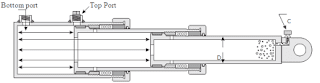
Construction of MLI
MLIs are installed in aircraft fuel tank and consists of
three parts,
Upper Outer part
Lower Outer part and
Inner assembly with graduation on it.
The outer assemblies made sealed tube which house the inner
assembly.
Upper Outer part

Upper outer part consists of tube, float assembly and
mounting. Float assembly contain magnet and installed over the tube. Float
assembly free to move along the tube and its motion stopped by collar at the
one end and mounting at another end. The tube assembly attached to mounting
assembly. Mounting assembly has opening in the center for inner assembly and is
attached to fuel tank.
Lower Outer part

Lower outer part is responsible for latching inner assembly. It consists of tube, mounting, collar and spring. The tube is installed in the mounting. The mounting contains collar and spring which help to latch and unlatch inner assembly. The mounting is attached to the aircraft fuel tank.
Inner Assembly i.e., MLI Rod

An inner assembly has graduated tube and graduations on tube show the contents of fuel in the tank. One end of inner assembly has magnet attached to it and this magnet attract to another magnet contain in float assembly when both assemblies brought together. A latch is bonded on bottom end of inner assembly and has slot for insertion of screwdriver for latching and unlatching.
Operation of MLI
The float assembly on upper outer part is held by the fuel in the aircraft fuel tank and moves along the tube when the level of fuel changes.
The magnet on inner assembly connects to the magnet in the float assembly when inner assembly reaches near to float assembly fuel level. The number of graduations marks that can be seen changes when the level of fuel changes, and therefore show the amount of fuel in the tank. When MLI not in use MLI rod kept latch inside of MLI tube.
When there is fuel in tank, float will be at particular level in the tank. As the MLI rod retract for reading and when it reaches to float level there be magnetic attraction between MLI rod and Float and this particular position of MLI rod gives the fuel quantity reading.
When there is zero fuel in the tank, float will be at lower
level. As MLI rod extend and retract for reading due to zero fuel in the tank
and magnetic force of attraction between MLI rod and float cause rod and
float move together along the MLI Tube.
Please Follow and Join us on below aircraft technical group there you can share your doubt.
Telegram
https://t.me/joinchat/NxLqTH2cTX9hMjM1
https://www.facebook.com/groups/304288677920172/?ref=share
https://www.instagram.com/invites/contact/?i=1tv1l3w2dcogj&utm_content=m7ttk5x
YouTube Channel
https://www.youtube.com/channel/UCwfz-cO2H3k8tnA_CMrMKtw

Comments
Post a Comment